Audio Circuit
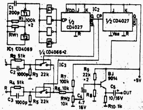
The stereo encoder circuit with discrete elements
Published:2012/8/27 22:15:00 Author:Ecco | Keyword: stereo encoder , discrete elements | From:SeekIC

In the figure IC1-4069, Y1 and Y2 form a oscillator with frequency in 76KHZ; then the frequency is isolated and shaped by Y3-Y6 to be sent into frequency-halving circuit composed of IC2 and dual JK flip-flop CD4027, then it will produce a symmetrical + /-38KHZ and 19KHZ square wave, in which the + /-38KHZ square wave is used for controlling the IC3 analog switch CD4066; the stereo audio signal is input to switch for switching modulation, then it is mixed with 19KHZ frequency signal and sent to FM modulator after being isolated by the transistor 9014. FM modulator circuit can refer to a variety of FM transmitter circuits at the site.
Reprinted Url Of This Article:
http://www.seekic.com/circuit_diagram/Audio_Circuit/The_stereo_encoder_circuit_with_discrete_elements.html
Print this Page | Comments | Reading(3)

Article Categories
power supply circuit
Amplifier Circuit
Basic Circuit
LED and Light Circuit
Sensor Circuit
Signal Processing
Electrical Equipment Circuit
Control Circuit
Remote Control Circuit
A/D-D/A Converter Circuit
Audio Circuit
Measuring and Test Circuit
Communication Circuit
Computer-Related Circuit
555 Circuit
Automotive Circuit
Repairing Circuit
Code: