Audio Circuit
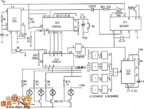
The bus station series indicator circuit
Published:2011/6/18 23:54:00 Author:Seven | Keyword: bus station, indicator | From:SeekIC

The circuit consists of the 555 single stable time delay circuit, a counter IC2, a decoding displayer IC3, a delay stereo circuit and so on. The single stable circuit consists of 555, Rt, Ct and so on, it's delayed time is td1=1.1RtCt. The counter can preset a 4-bit binary reversible counter CD4516. IC3 is a 4-bit lock-storage 4-16 line decoder. The stereo circuit consists of the music integrated circuit IC4(KD9300) and the loudspeaker. When the switch AN is pressed, the delaying pulse, which is output by IC1, is added on the counter IC2, and IC2 does the +1(or -1) counting, and the output of Q1~Q4 comes into IC3 for decoding.
Reprinted Url Of This Article:
http://www.seekic.com/circuit_diagram/Audio_Circuit/The_bus_station_series_indicator_circuit.html
Print this Page | Comments | Reading(3)

Article Categories
power supply circuit
Amplifier Circuit
Basic Circuit
LED and Light Circuit
Sensor Circuit
Signal Processing
Electrical Equipment Circuit
Control Circuit
Remote Control Circuit
A/D-D/A Converter Circuit
Audio Circuit
Measuring and Test Circuit
Communication Circuit
Computer-Related Circuit
555 Circuit
Automotive Circuit
Repairing Circuit
Code: