Audio Circuit
RADIO_DIRECTION_FINDER_
Published:2009/7/10 4:46:00 Author:May | From:SeekIC


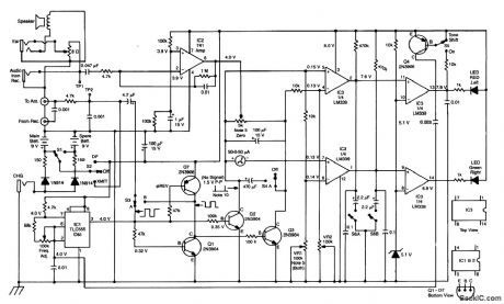
This RDF circuit consists of a square-wave oscillator (IC1), which switches two antennas alternately at an audio rate. A phase detector (Q1, 2, 3, 7) is used to compare receiver output amplified by IC2 with the reference phase from IC2 with the reference phase from IC1. A 50-μA meter is used as a left-right indicator. IC3 is a comparator used to drive indicator LEDs.
Reprinted Url Of This Article:
http://www.seekic.com/circuit_diagram/Audio_Circuit/RADIO_DIRECTION_FINDER_.html
Print this Page | Comments | Reading(3)

Article Categories
power supply circuit
Amplifier Circuit
Basic Circuit
LED and Light Circuit
Sensor Circuit
Signal Processing
Electrical Equipment Circuit
Control Circuit
Remote Control Circuit
A/D-D/A Converter Circuit
Audio Circuit
Measuring and Test Circuit
Communication Circuit
Computer-Related Circuit
555 Circuit
Automotive Circuit
Repairing Circuit
Code: