Audio Circuit
Linear_FM_detector
Published:2009/7/24 23:43:00 Author:Jessie | From:SeekIC


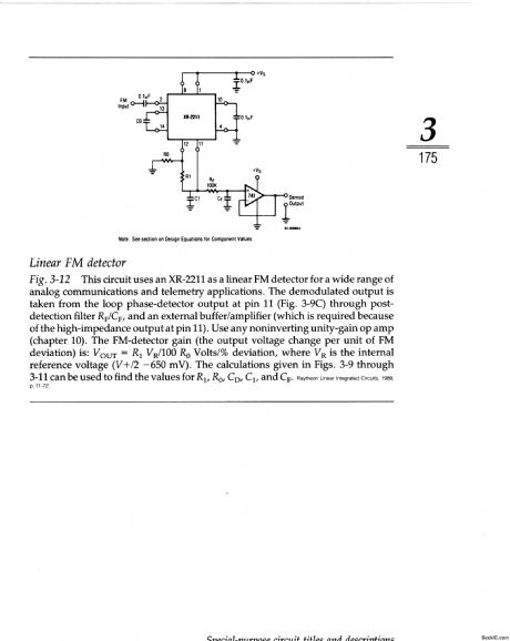
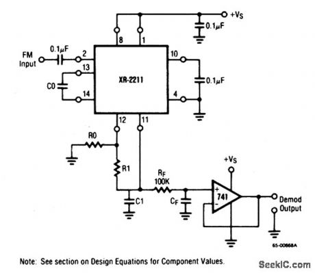
This circuit uses an XR-2211 as a linear FM detector for a wide range of analog communications and telemetry applications. The demodulated output is taken from the loop phase-detector output at pin 11 (Fig. 3-9C) through post-detection filter RF/CF, and an external buffer/amplifier (which is required because of the high-impedance output at pin 11). Use any noninverting unity-gain op amp (chapter 10). The FM-detector gain (the output voltage change per unit of FM deviation) is: VOUT=R1 VR/100 R0 Volts/% deviation, where VR is the internal reference voltage (V+/2 -650 mV). The calculations given in Figs. 3-9 through 3-11 can be used to find the values for R1, R0, CD, C1, and CF.
Reprinted Url Of This Article:
http://www.seekic.com/circuit_diagram/Audio_Circuit/Linear_FM_detector.html
Print this Page | Comments | Reading(3)

Article Categories
power supply circuit
Amplifier Circuit
Basic Circuit
LED and Light Circuit
Sensor Circuit
Signal Processing
Electrical Equipment Circuit
Control Circuit
Remote Control Circuit
A/D-D/A Converter Circuit
Audio Circuit
Measuring and Test Circuit
Communication Circuit
Computer-Related Circuit
555 Circuit
Automotive Circuit
Repairing Circuit
Code: