Audio Circuit
FM wireless headphone circuit
Published:2012/8/20 22:08:00 Author:Ecco | Keyword: FM , wireless headphone | From:SeekIC


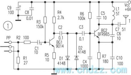
Figure 1 is a transmitting circuit of wireless headset, the audio signal obtained by television headphone jack bu passing stereo headphone plug is amplified by BG2, then it is amplitude limited by limiter circuit composed of D1, D2, C2, C3 and sent to high frequency oscillator composed of BG2; the modulated FM signal is coupled by C7 and emitted by antenna. Figure 2 is a receiving circuit which uses dedicated FM receiver module IC1 TDA7021T as the core. The demodulated audio signal is output from the foot sent to IC2 LM386 for power amplification and promote the headphones sound. Transistor BG 9018 form the high - frequency amplifier stage in order to improve the reception sensitivity.
Reprinted Url Of This Article:
http://www.seekic.com/circuit_diagram/Audio_Circuit/FM_wireless_headphone_circuit.html
Print this Page | Comments | Reading(3)

Article Categories
power supply circuit
Amplifier Circuit
Basic Circuit
LED and Light Circuit
Sensor Circuit
Signal Processing
Electrical Equipment Circuit
Control Circuit
Remote Control Circuit
A/D-D/A Converter Circuit
Audio Circuit
Measuring and Test Circuit
Communication Circuit
Computer-Related Circuit
555 Circuit
Automotive Circuit
Repairing Circuit
Code: