Audio Circuit
FM_remote_speaker_system
Published:2009/7/24 4:41:00 Author:Jessie | From:SeekIC


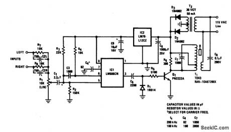
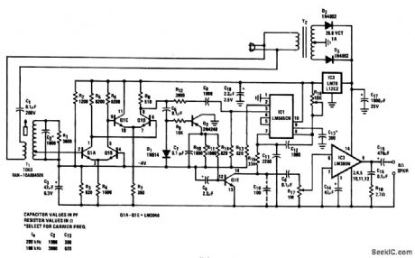
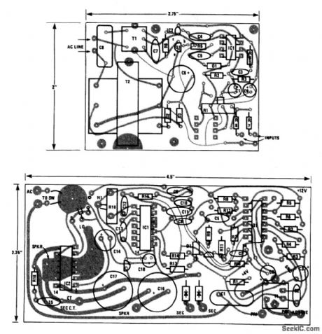
This complete carrier system is suitable for(high-qualit transmission of speech or music, and will operate from any ac outlet anywhere on a one-acre homesite. The frequency response is 20 to 20,000 Hz and THD_is under 0.5% for speech and music program material. The transmitter (Fig. 2-62A and 2-62C) is plugged into the ac line at a radio or stereo-system source The signal for the transmitter is ideally taken from the Monitor or Tape out connectors provided on component-system hi-fi receivers. The receiver (Fig 2-62B and 2:62B) amplifier ,limits, and demodulates the received FM signal in the presence of line-transient interference (sometimes as high as several hundred volts peak). The receiver also provides audio-mute in the absence of a carrier and 2.5-W audio output to a speaker. Transmitter carrier frequency fc is fixed near 100 or 200 kHz by C4/C7.The exact frequency is not important because T1 for both transmitter and receiver are tuned for maximum coupling to and from the ac line. Of course, both receiver and transmitter must be at the same frequency. With both transmitter and receiver operating (modulation is not necessary), tune the transmitter T1 for maximum, as measured with an ac VTVM at the receiver T1 secondary. Then tune the receiver T1 for maximum. Repeat as necessary. Set the receiver PLL free-running frequency with R16 near the center of its range. Rotate slowly in either direction until the PLL loses lock (as shown by a sharp increase in noise and a distorted output). Note the position of R16, and then repeat, rotating in the other direction. Note the new position, then center R16 between the two noted positions (a fine adjustment can be made for minimum noise if there is an SCR dimmer used in the house). Connect an audio signal to the transmitter input, and adjust RI for a maximum signal of about 0.1 V rms at pin 5 of IC1. This completes the adjustment. However, it might be necessary to readjust the receiver T1 slightly to minimize noise from SCR dimmers.
Reprinted Url Of This Article:
http://www.seekic.com/circuit_diagram/Audio_Circuit/FM_remote_speaker_system.html
Print this Page | Comments | Reading(3)

Article Categories
power supply circuit
Amplifier Circuit
Basic Circuit
LED and Light Circuit
Sensor Circuit
Signal Processing
Electrical Equipment Circuit
Control Circuit
Remote Control Circuit
A/D-D/A Converter Circuit
Audio Circuit
Measuring and Test Circuit
Communication Circuit
Computer-Related Circuit
555 Circuit
Automotive Circuit
Repairing Circuit
Code: