Audio Circuit
Dual Track Loudspeaker Protection Circuit
Published:2011/7/18 0:46:00 Author:Sue | Keyword: Dual Track, Loudspeaker, Protection | From:SeekIC

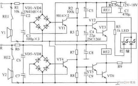
The picture shows the dual track loudspeaker protection circuit. It is designed that the left and right tracks are working independently. In the picture(to take the left track for example), R2, C4 and VT2,VT3 compose starting delay circuit which can prevent the large starting current from shocking the loudspeaker.
Component choice:We can choose Φ3mm high-brightness two-tone LED as LED. Because of the reason that LED has different working currents, so R5,R9 have adjustable parameters. At the same time, LED and current-limiting resistor R5,R9 are connected to relay RE1,RE2 in parallel, which can prevent inverse peak voltage and can prevent VT2,VT3,VT5,VT6 frombeing punctured. The best choice for C4,C9 is low-leakage tantalum capacitor.
Reprinted Url Of This Article:
http://www.seekic.com/circuit_diagram/Audio_Circuit/Dual_Track_Loudspeaker_Protection_Circuit.html
Print this Page | Comments | Reading(3)

Article Categories
power supply circuit
Amplifier Circuit
Basic Circuit
LED and Light Circuit
Sensor Circuit
Signal Processing
Electrical Equipment Circuit
Control Circuit
Remote Control Circuit
A/D-D/A Converter Circuit
Audio Circuit
Measuring and Test Circuit
Communication Circuit
Computer-Related Circuit
555 Circuit
Automotive Circuit
Repairing Circuit
Code: