Audio Circuit
Computer Mainboard ATXPWROK Control Circuit
Published:2011/7/19 7:52:00 Author:Sue | Keyword: Computer Mainboard, Control | From:SeekIC


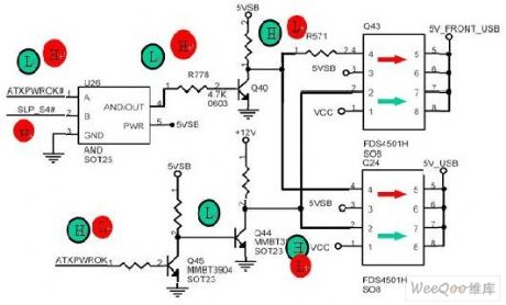
When it is working, ATXPWROK is high level. Q45 is connected and Q44 is disconnected. +12V voltage will be put on Q43 and Q24's pin 2 through resistors, that is binary channels MOS tube's N channel's control pin is high level and the channel is connected. At that time, VCC voltage will output 5V USB voltage from pin7,pin8 through N-type MOS tube. At the same time, when ATXPWROK is high level, ATXPWROK # is low level, then ANT GATE U26 outputs low level. Q40 is disconnected and will output high level control signal to Q43 and 24's pin 4, that is binary channel MOS tube's P-type channel is disconnected. Then pin 5, pin 6 have no output current, that is 5VSB doesn't supply 5VUSB voltage.
Reprinted Url Of This Article:
http://www.seekic.com/circuit_diagram/Audio_Circuit/Computer_Mainboard_ATXPWROK_Control_Circuit.html
Print this Page | Comments | Reading(3)

Article Categories
power supply circuit
Amplifier Circuit
Basic Circuit
LED and Light Circuit
Sensor Circuit
Signal Processing
Electrical Equipment Circuit
Control Circuit
Remote Control Circuit
A/D-D/A Converter Circuit
Audio Circuit
Measuring and Test Circuit
Communication Circuit
Computer-Related Circuit
555 Circuit
Automotive Circuit
Repairing Circuit
Code: