Audio Circuit
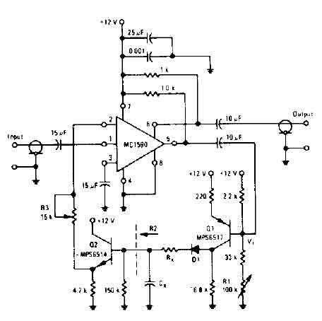
Audio compressor circuit
Published:2012/9/10 20:57:00 Author:Ecco | Keyword: Audio compressor | From:SeekIC

The amplifier drives the base of a common emitter PNP MPS6517 operating with a voltage gain of about 20. RL control varies the quiescent point of the transistor Q, so that varying amounts of signal exceed the level of V r, diode D 1 rectifies the positive peaks Ql output is only when these peaks are more larger than r V ' 7. 0 volts. The result is filtered ex Rx. s, controls the charging time constant or time of attack. Cx is involved in two loading and unloading. R2 (150 K, the input resistance of the emitter-follower Q2) controls the decay time.
Source: discovercircuits
Reprinted Url Of This Article:
http://www.seekic.com/circuit_diagram/Audio_Circuit/Audio_compressor_circuit.html
Print this Page | Comments | Reading(3)

Article Categories
power supply circuit
Amplifier Circuit
Basic Circuit
LED and Light Circuit
Sensor Circuit
Signal Processing
Electrical Equipment Circuit
Control Circuit
Remote Control Circuit
A/D-D/A Converter Circuit
Audio Circuit
Measuring and Test Circuit
Communication Circuit
Computer-Related Circuit
555 Circuit
Automotive Circuit
Repairing Circuit
Code: