Audio Circuit
Audio Clipping Indicator
Published:2012/9/26 21:18:00 Author:muriel | Keyword: Audio Clipping, Indicator | From:SeekIC

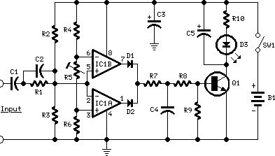
This Audio Clipping Indicator circuit was intended to detect clipping in preamp stages, mixers, amplifiers etc. and can be used as a separate, portable unit, to signal by means of a LED when the output wave form of a particular audio stage is “clipping” i.e. is reaching the onset of its maximum permitted peak-to-peak voltage value before an overload is occurring. This will help the operator in preventing severe, audible distortion to be generated through the audio equipment chain.This unit is particularly useful in signaling overload of the input stages in mixers, PA or musical instruments amplification chains, but is also suited to power amplifiers. A careful setting of Trimmer R5 will allow triggering of the LED with a wide range of peak-to-peak input voltages, in order to suit different requirements.
Unfortunately, an oscilloscope and a sine wave frequency generator are required to accurately setup this circuit. Obviously, the unit can be embedded into an existing mixer, preamp or power amplifier, and powered by the internal supply rails in the 9 – 30V range. The power supply can also be obtained from higher voltage rails provided suitable R/C cells are inserted. SW1 and B1 must obviously be omitted.
Clipping Indicator circuit diagram
Reprinted Url Of This Article:
http://www.seekic.com/circuit_diagram/Audio_Circuit/Audio_Clipping_Indicator.html
Print this Page | Comments | Reading(3)

Article Categories
power supply circuit
Amplifier Circuit
Basic Circuit
LED and Light Circuit
Sensor Circuit
Signal Processing
Electrical Equipment Circuit
Control Circuit
Remote Control Circuit
A/D-D/A Converter Circuit
Audio Circuit
Measuring and Test Circuit
Communication Circuit
Computer-Related Circuit
555 Circuit
Automotive Circuit
Repairing Circuit
Code: