Audio Circuit
ADJUSTABLE_SQUARE_WAVES
Published:2009/7/15 4:57:00 Author:Jessie | From:SeekIC

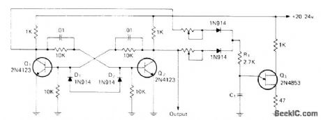
Q1 and Q2 form flip-flop, with UJT Q3 connected as time delay. When power is applied, one flip-flop transistor conducts and C1 charges through one pot and diode. When C1 reaches firing voltage of UJT, it conducts and resulting output pulse triggers flip-flop, Sequence of events now repeats, with C1 charging through other diode. By proper selection of C1 and pot values, circuit becomes square-wave generator with each pot controlling duration of one half-cycle. With one pot replaced by fixed resistor, circuit becomes pulse generator with other pot controlling pulse-repetition rate. If equal-value fixed resistors replace pots and R1 is changed to pot, circuit becomes symmetrical square-wave generator with pot controlling frequency,-I. Math, Math's Notes, CQ, April 1974, p 64-65 and 91-92.
Reprinted Url Of This Article:
http://www.seekic.com/circuit_diagram/Audio_Circuit/ADJUSTABLE_SQUARE_WAVES.html
Print this Page | Comments | Reading(3)

Article Categories
power supply circuit
Amplifier Circuit
Basic Circuit
LED and Light Circuit
Sensor Circuit
Signal Processing
Electrical Equipment Circuit
Control Circuit
Remote Control Circuit
A/D-D/A Converter Circuit
Audio Circuit
Measuring and Test Circuit
Communication Circuit
Computer-Related Circuit
555 Circuit
Automotive Circuit
Repairing Circuit
Code: