Amplifier Circuit
two transistor operation
Published:2012/10/12 22:42:00 Author:muriel | Keyword: two transistor | From:SeekIC

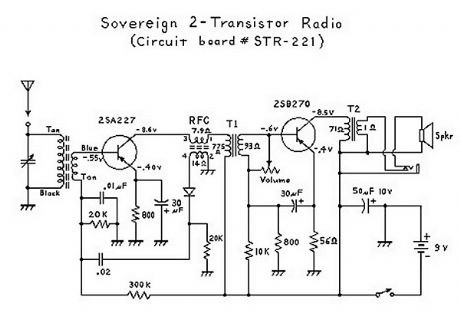
It has been interesting analyzing these radios. You have to give the Japanese credit for even making a radio that can drive a speaker with only 2 transistors! Basically, the first transistor (Q1) performs double-duty. It first acts as an RF amplifier, with some of the signal being fed back to the antenna coil to provide some regeneration for better selectivity and sensitivity. (This also results in a non-linear amplification of the signal which results in noticeable distortion.) The RF (radio frequency) signal is then rectified ( detected ) by the diode, and then the resultant audio signal is fed back to the base of the first transistor where it acts as the first AF (audio frequency) amplifier. (This is called a reflex circuit.) The audio signal is then fed through an interstage transformer to Q2 (the second transistor). The transformer provides impedance matching. The second transistor acts as a power amplifier, with the output signal going through an audio output transformer (to provide impedance matching again), and then finally to the speaker. Everything about this circuit is designed to provide maximimum gain; consequently there is no AGC (automatic gain control), and stronger stations come in a lot louder than weaker stations; unlike 6-transistor (or more) radio circuits which have an AGC circuit or function.
Reprinted Url Of This Article:
http://www.seekic.com/circuit_diagram/Amplifier_Circuit/two_transistor_operation.html
Print this Page | Comments | Reading(3)

Article Categories
power supply circuit
Amplifier Circuit
Basic Circuit
LED and Light Circuit
Sensor Circuit
Signal Processing
Electrical Equipment Circuit
Control Circuit
Remote Control Circuit
A/D-D/A Converter Circuit
Audio Circuit
Measuring and Test Circuit
Communication Circuit
Computer-Related Circuit
555 Circuit
Automotive Circuit
Repairing Circuit
Code: