Amplifier Circuit
Voltage_controlled_resistor
Published:2009/7/17 3:05:00 Author:Jessie | From:SeekIC

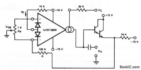
This circuit uses one section of an XR-13600 (Fig. 11-1B) as a single-ended voltage-controlled resistor. A signal applied at RX generates an input to the XR-13600, which is then multiplied by the gm of the amplifier to produce an output current. The resulting resistor or RX = (R + RA)/(gm RA), where gm 19.2 IB at 25℃. Notice that the attenuation of VO by R and RA is necessary to maintain the input within the linear range of the XR-13600 input. EXAP corporation Dalabook 1990 p 5 25
Reprinted Url Of This Article:
http://www.seekic.com/circuit_diagram/Amplifier_Circuit/Voltage_controlled_resistor.html
Print this Page | Comments | Reading(3)

Article Categories
power supply circuit
Amplifier Circuit
Basic Circuit
LED and Light Circuit
Sensor Circuit
Signal Processing
Electrical Equipment Circuit
Control Circuit
Remote Control Circuit
A/D-D/A Converter Circuit
Audio Circuit
Measuring and Test Circuit
Communication Circuit
Computer-Related Circuit
555 Circuit
Automotive Circuit
Repairing Circuit
Code: