Amplifier Circuit
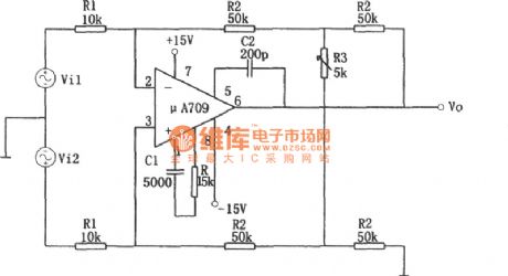
Variable gain differential amplifier circuit composed of the μA709
Published:2011/6/27 5:14:00 Author:Rebekka | Keyword: Variable gain, differential amplifier | From:SeekIC

The figure shows variable gain differential amplifier circuit composed of the μA709. The biggest advantage of this circuit is to maintain common-mode rejection and keep the ratio KCMR in the same premise. The differential gain can be achieved continuously adjustable. The biggest advantage of this circuit is to maintain common-mode rejection ratio KCMR the same premise, the differential gain can be achieved continuously adjustable. The circuit of the basic relationship is: Vo =- (2R2/R1) · (1 + R2/R3) · (Vi1-Vi2) Av = Vo / (Vi1 a Vi2) =- (2R2/R1) · (1 + R2 / R3) When R1 = 10kΩ, R2 = 50kΩ, R3 = 5kΩ when, Av =- 110. μA709 integrated chip electrical parameters (VD = ± 15V, TA = 25 ℃).
Reprinted Url Of This Article:
http://www.seekic.com/circuit_diagram/Amplifier_Circuit/Variable_gain_differential_amplifier_circuit_composed_of_the_μA709.html
Print this Page | Comments | Reading(3)

Article Categories
power supply circuit
Amplifier Circuit
Basic Circuit
LED and Light Circuit
Sensor Circuit
Signal Processing
Electrical Equipment Circuit
Control Circuit
Remote Control Circuit
A/D-D/A Converter Circuit
Audio Circuit
Measuring and Test Circuit
Communication Circuit
Computer-Related Circuit
555 Circuit
Automotive Circuit
Repairing Circuit
Code: