Amplifier Circuit
VARIABLE_Q_AF
Published:2009/7/3 2:28:00 Author:May | From:SeekIC


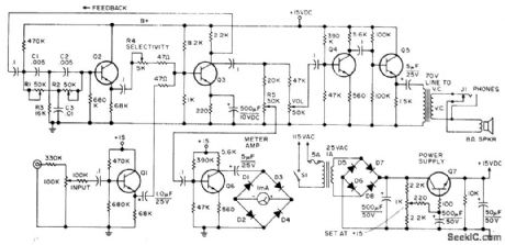
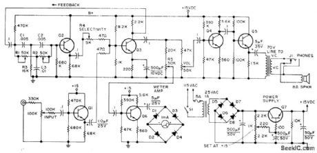
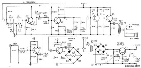
Consists of tuned amplifier having inverse feedback, connected so bandwidth at -6 dB is variablefrom 50 to 400 Hz for center frequency of 1 kHz. Improves selectivity of amateur receivers. Audio from receiver is applied to inverter Q3 through Q1. Part of inverted signal is fed back to twin-T network R1-R2-R3-C1-C2-C3 which has high impedance to ground except at its resonant frequency. Unattenuated signal goes through Q2 for adding to uninverted output at base of Q3. Degree of cancellation by two out-of-phase signals feeding Q3 is controned by R4 to adjust selectivity Filtered output is boosted by Q4 and Q5,Article covers construction,calibration,and operation,Q1-Q6 are GE-20,and Q7 is GE-14 or GE-28,-c,Townsend,A Variable Q Audio Fillter,73 Magazine,Feb,1974, p 54-56.
Reprinted Url Of This Article:
http://www.seekic.com/circuit_diagram/Amplifier_Circuit/VARIABLE_Q_AF.html
Print this Page | Comments | Reading(3)

Article Categories
power supply circuit
Amplifier Circuit
Basic Circuit
LED and Light Circuit
Sensor Circuit
Signal Processing
Electrical Equipment Circuit
Control Circuit
Remote Control Circuit
A/D-D/A Converter Circuit
Audio Circuit
Measuring and Test Circuit
Communication Circuit
Computer-Related Circuit
555 Circuit
Automotive Circuit
Repairing Circuit
Code: