Amplifier Circuit
The sound control relay circuit
Published:2011/7/23 22:16:00 Author:Seven | Keyword: sound control relay | From:SeekIC

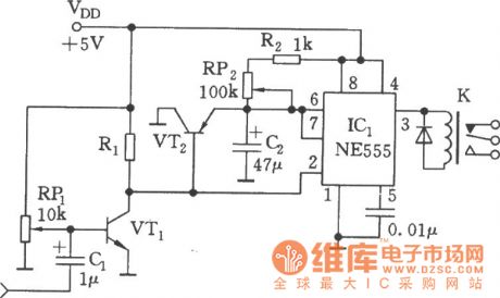
See as the figure, the circuit consists of the sound detection circuit and single steady trigger circuit, the relay is the executing component. VT1 finish the magnifying job of the input audio signal, when signals come, the 555 is reset, K is pulling in, VT2 is conducting, the electricity on C2 is released by the discharging tube and VT2 in 555. After the sound is gone, both VT1 and VT2 are blocked, C2 charges them through R2 and RP2, the contemporary stable time of the single stable circuit is td =1.1(R2+RP2)C2, the delaying time is 0.05~0.5S which can be adjusted by RP2.
Reprinted Url Of This Article:
http://www.seekic.com/circuit_diagram/Amplifier_Circuit/The_sound_control_relay_circuit.html
Print this Page | Comments | Reading(3)

Article Categories
power supply circuit
Amplifier Circuit
Basic Circuit
LED and Light Circuit
Sensor Circuit
Signal Processing
Electrical Equipment Circuit
Control Circuit
Remote Control Circuit
A/D-D/A Converter Circuit
Audio Circuit
Measuring and Test Circuit
Communication Circuit
Computer-Related Circuit
555 Circuit
Automotive Circuit
Repairing Circuit
Code: