Amplifier Circuit
The industrial time relay circuit
Published:2011/7/21 1:51:00 Author:Seven | Keyword: time relay circuit | From:SeekIC


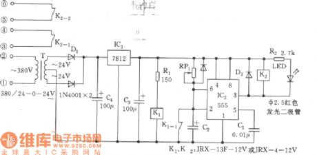
See as the figure, the time relay is to replace JSK, which is designed for the transistor time relay. The circuit includes the step-down regulated voltage source(+12V), 555 single stable circuit and relay control, etc. 555, RP1 and C2 compose the single stable delay circuit, the time td =l.1RP1C2. When the power supply is on, as the 2-pin is in a low LEV, the 555 is reset, K2 is still, when C2 is charged to 2/3VDD by RP1, 3-pin is in a low LEV, K2 is pulling in, which connects with the contactors of K2-1 and K2-2.
Reprinted Url Of This Article:
http://www.seekic.com/circuit_diagram/Amplifier_Circuit/The_industrial_time_relay_circuit.html
Print this Page | Comments | Reading(3)

Article Categories
power supply circuit
Amplifier Circuit
Basic Circuit
LED and Light Circuit
Sensor Circuit
Signal Processing
Electrical Equipment Circuit
Control Circuit
Remote Control Circuit
A/D-D/A Converter Circuit
Audio Circuit
Measuring and Test Circuit
Communication Circuit
Computer-Related Circuit
555 Circuit
Automotive Circuit
Repairing Circuit
Code: