Amplifier Circuit
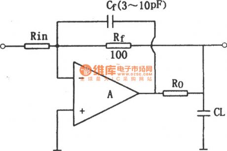
The compensation circuit of op amp output capacitor
Published:2011/6/27 21:52:00 Author:Rebekka | Keyword: Op amp output capacitor, Compensation circuit | From:SeekIC

Put a resistance Ro at the output terminal of the series. The load capacitance CL and amplifying circuit is separated, it is shown in figure, connect the feedback resistance Rf in the back of the Ro. This can compensate the dc attenuation. The feedback capacitor Cf will reduce the high frequency closed-loop voltage magnification. The method of selecting Cf is: Make amplifier circuit of the unit gain the RongKang Xcf frequency fT 10, Rf/Xf = l / (2) fTCf PI. Usually, Ro = 50 ~ 200 Ω, Cf is 3 ~ 10 pF. It is shown in figure, the op-amp output capacitance of the compensation circuit diagram.
Reprinted Url Of This Article:
http://www.seekic.com/circuit_diagram/Amplifier_Circuit/The_compensation_circuit_of_op_amp_output_capacitor.html
Print this Page | Comments | Reading(3)

Article Categories
power supply circuit
Amplifier Circuit
Basic Circuit
LED and Light Circuit
Sensor Circuit
Signal Processing
Electrical Equipment Circuit
Control Circuit
Remote Control Circuit
A/D-D/A Converter Circuit
Audio Circuit
Measuring and Test Circuit
Communication Circuit
Computer-Related Circuit
555 Circuit
Automotive Circuit
Repairing Circuit
Code: