Amplifier Circuit
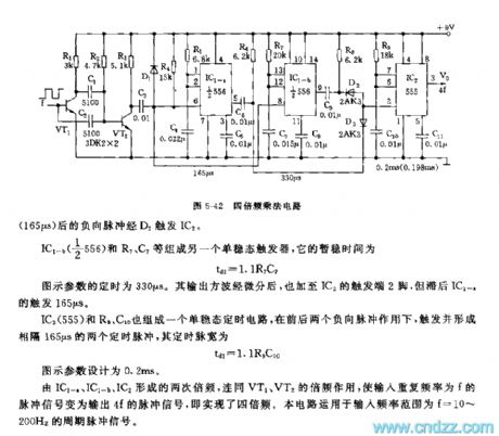
The 555 quadruple frequency multiply circuit
Published:2011/7/20 7:28:00 Author:Seven | Keyword: quadruple frequency, multiply circuit | From:SeekIC

This multiply circuit can convert the period sequence of f1 into output pulse signal of f0=4f1, which is a quadruple frequency circuit, see as figure 5-42. The circuit includes the differentiation twice frequency circuit, single stable timing circuit and double frequency circuit and so on. VT1, R1, C1, C2 and R2 compose the phase inverting amplifier and differentiation circuit. C2, R2 and C1, R2 compose the differentiation circuit which forms 2 undershoot narrowing pulses, the first doubling is done at the collecting electrode of VT2.
Reprinted Url Of This Article:
http://www.seekic.com/circuit_diagram/Amplifier_Circuit/The_555_quadruple_frequency_multiply_circuit.html
Print this Page | Comments | Reading(3)

Article Categories
power supply circuit
Amplifier Circuit
Basic Circuit
LED and Light Circuit
Sensor Circuit
Signal Processing
Electrical Equipment Circuit
Control Circuit
Remote Control Circuit
A/D-D/A Converter Circuit
Audio Circuit
Measuring and Test Circuit
Communication Circuit
Computer-Related Circuit
555 Circuit
Automotive Circuit
Repairing Circuit
Code: