Amplifier Circuit
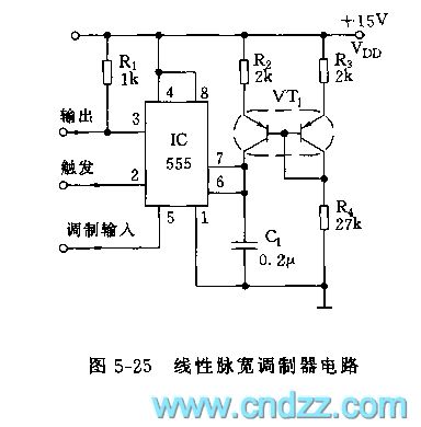
The 555 linear PWM circuit
Published:2011/7/20 7:47:00 Author:Seven | Keyword: linear PWM circuit | From:SeekIC

See as figure 5-25, IC(555), R2, VT1 and C1 compose the controllable single steady circuit, the contemporary pulse wavelength is in backward proportion to the input modulation signal, the higher the modulation LEV is, the narrower the pulse will be. VT1 is a symmetric dual triode BT51, which composes the mirror image current source with R2 and R3, and the mirror image makes the charge current of C1 keep linear in the contemporary stable period, the linearity is ±0.2%.
Reprinted Url Of This Article:
http://www.seekic.com/circuit_diagram/Amplifier_Circuit/The_555_linear_PWM_circuit.html
Print this Page | Comments | Reading(3)

Article Categories
power supply circuit
Amplifier Circuit
Basic Circuit
LED and Light Circuit
Sensor Circuit
Signal Processing
Electrical Equipment Circuit
Control Circuit
Remote Control Circuit
A/D-D/A Converter Circuit
Audio Circuit
Measuring and Test Circuit
Communication Circuit
Computer-Related Circuit
555 Circuit
Automotive Circuit
Repairing Circuit
Code: