Amplifier Circuit
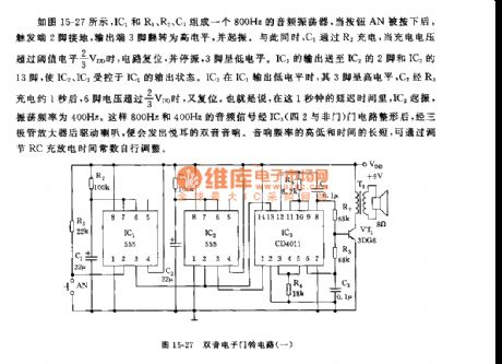
The 555 dual electric door bell circuit (1)
Published:2011/7/20 7:58:00 Author:Seven | Keyword: electric door bell | From:SeekIC

See as figure 15-27, IC1, R1, R2 and C1 compose a 800Hz audio oscillator circuit, when AN is pressed, the 2-pin of the trigger is connected with the earth, the 3-pin of the output terminal is reversed to be in a high LEV and starting to oscillate. Meanwhile, C1 is charged by R2, when the charge voltage is over the threshold LEV of 2/3VDD, the circuit is reset and stopping oscillating, the 3-pin is in a low LEV. The output of IC1 is sent to the 2-pin of IC2 and 13-pin of IC3, which makes IC2 and IC3 to be controlled by the output state of IC1.
Reprinted Url Of This Article:
http://www.seekic.com/circuit_diagram/Amplifier_Circuit/The_555_dual_electric_door_bell_circuit_1.html
Print this Page | Comments | Reading(3)

Article Categories
power supply circuit
Amplifier Circuit
Basic Circuit
LED and Light Circuit
Sensor Circuit
Signal Processing
Electrical Equipment Circuit
Control Circuit
Remote Control Circuit
A/D-D/A Converter Circuit
Audio Circuit
Measuring and Test Circuit
Communication Circuit
Computer-Related Circuit
555 Circuit
Automotive Circuit
Repairing Circuit
Code: