Amplifier Circuit
STEREO_AUDIO_COMPRESSOR
Published:2009/7/13 2:28:00 Author:May | From:SeekIC


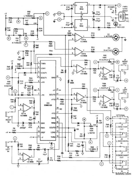
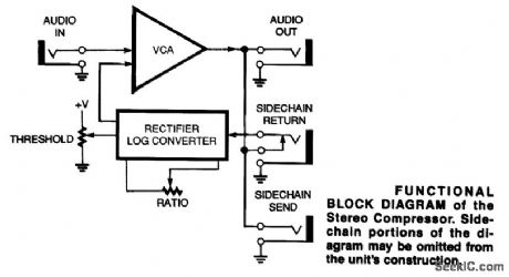
The block diagram of the stereo compressor is shown. The input signal is fed to a voltage-con-trolled amplifier (VCA) that has a nominal gain of unity. Some of the output signal is fed to a precision rectifier followed by a logarithmic converter circuit. The output of this block is a dc voltage proportional to the log of the average level of the input signal. By sending some of this dc control voltage to the VCA, the gain of the VCA is automatically reduced when the input signal exceeds a user-determined threshold level. It is important to note that the signal level is determined after the VCA and not before. This allows the output level to increase and sound normal, but not increase as much as the input signal does. By varying the amount of feedback, the compression ratio is adjusted, which, in conjunction with the THRESHOLD control, determines the operating characteristics of the compressor. The optional sidechain jacks permit external processing of the audio signal or substitution of a completely different audio signal as the control signal. This add-on circuitry lets the user ex-periment and achieve some useful audio effects.
Reprinted Url Of This Article:
http://www.seekic.com/circuit_diagram/Amplifier_Circuit/STEREO_AUDIO_COMPRESSOR.html
Print this Page | Comments | Reading(3)

Article Categories
power supply circuit
Amplifier Circuit
Basic Circuit
LED and Light Circuit
Sensor Circuit
Signal Processing
Electrical Equipment Circuit
Control Circuit
Remote Control Circuit
A/D-D/A Converter Circuit
Audio Circuit
Measuring and Test Circuit
Communication Circuit
Computer-Related Circuit
555 Circuit
Automotive Circuit
Repairing Circuit
Code: