Amplifier Circuit
Ramp_pulse_VCO
Published:2009/7/17 3:22:00 Author:Jessie | From:SeekIC

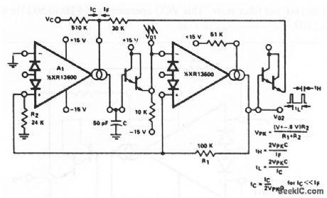
This circuit is similar to that of Fig. 11-13, except that the outputs are ramps and pulses. When V02 is high, IF is added to IC to increase the bias current of amplifier A1, and thus to increase the charging rate of capacitor C. When V02 is low, IF goes to zero and the capacitor discharge current is set by IC, EXAR Corporaton Databook 1990 p 5-255
Reprinted Url Of This Article:
http://www.seekic.com/circuit_diagram/Amplifier_Circuit/Ramp_pulse_VCO.html
Print this Page | Comments | Reading(3)

Article Categories
power supply circuit
Amplifier Circuit
Basic Circuit
LED and Light Circuit
Sensor Circuit
Signal Processing
Electrical Equipment Circuit
Control Circuit
Remote Control Circuit
A/D-D/A Converter Circuit
Audio Circuit
Measuring and Test Circuit
Communication Circuit
Computer-Related Circuit
555 Circuit
Automotive Circuit
Repairing Circuit
Code: