Amplifier Circuit
PHOTOMULTIPLIER_LASER_RECEIVER_WITH_VIDEO_AMPLIFIER_
Published:2009/7/14 12:00:00 Author:May | From:SeekIC

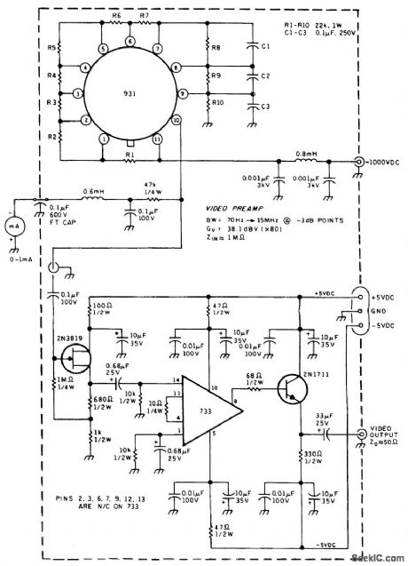
This is a circuit diagram for the inexpensive 931 side-looking PMT and its resistor divider network. This circuit maintains the proper voltages for the dynodes. The capacitors across the last three network resistors improve the frequency response of the PMT to modulated signals. A milliammeter in the PMT anode circuit registers the average PMT current under the medium to high illumination encountered during diagnostic tests. A PMT preamplifier uses a 733 (or equivalent) wideband amplifier. Because the demodulated signal can be either a direct baseband signal or a baseband signal modulated onto a subcarrier, the preamplifier must be capable of amplifying all the demodulated signal frequencies. The preamplifier is designed for a 70-Hz to 15-MHz bandwidth at the -3-dB points and for a gain of 80. Because the signal detection circuits will probably be placed in a separate housing, the video preamplifier is designed to drive a 50-Ω cable. With the high-current multiplication inherent in the PMT, the PMT noise will predominate over the video preamplifier IC noise.
Reprinted Url Of This Article:
http://www.seekic.com/circuit_diagram/Amplifier_Circuit/PHOTOMULTIPLIER_LASER_RECEIVER_WITH_VIDEO_AMPLIFIER_.html
Print this Page | Comments | Reading(3)

Article Categories
power supply circuit
Amplifier Circuit
Basic Circuit
LED and Light Circuit
Sensor Circuit
Signal Processing
Electrical Equipment Circuit
Control Circuit
Remote Control Circuit
A/D-D/A Converter Circuit
Audio Circuit
Measuring and Test Circuit
Communication Circuit
Computer-Related Circuit
555 Circuit
Automotive Circuit
Repairing Circuit
Code: