Amplifier Circuit
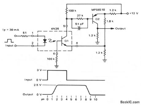
Optically_coupled_Schmitt_trigger
Published:2009/7/22 22:07:00 Author:Jessie | From:SeekIC

This circuit uses the 4N26 transistor as part of a Schmitt trigger. When Q1 conducts in response to an input pulse, Q2 conducts and the output is high.When the input pulse is removed from the 4N26, Q1 shuts off, and the output is low. With the values shown, the tum-off delay is about 2 μs, and the turn-off delay is about 6 ps. Speed can be improved by lowering the value of the Q1 base resistance from 100 kΩ, but the drive requirements must be increased.
Reprinted Url Of This Article:
http://www.seekic.com/circuit_diagram/Amplifier_Circuit/Optically_coupled_Schmitt_trigger.html
Print this Page | Comments | Reading(3)

Article Categories
power supply circuit
Amplifier Circuit
Basic Circuit
LED and Light Circuit
Sensor Circuit
Signal Processing
Electrical Equipment Circuit
Control Circuit
Remote Control Circuit
A/D-D/A Converter Circuit
Audio Circuit
Measuring and Test Circuit
Communication Circuit
Computer-Related Circuit
555 Circuit
Automotive Circuit
Repairing Circuit
Code: