Amplifier Circuit
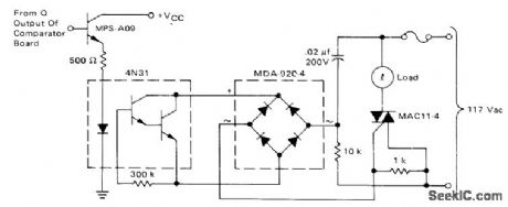
OUTPUT_CONTROL_FOR_CLOCK_COMPARATOR
Published:2009/7/13 22:45:00 Author:May | From:SeekIC

Circuit triggers 10-A triac when Q output of comparator-driven flip-flop is logic 1. LED in optoisolator is then energized, activating phototransistor pair for driving gate circuit of triac through diode bridge. Trigger voltage of triac is positive for first quadrant and negative for third quadrant, to give maximum sensitivity of triac control.-D. Aldridge and A. Mouton, Industrial Clock/Timor Featuring Back-Up Power Supply Operation,” Motorola, Phoenix, AZ, 1974, AN-718A, p 7.
Reprinted Url Of This Article:
http://www.seekic.com/circuit_diagram/Amplifier_Circuit/OUTPUT_CONTROL_FOR_CLOCK_COMPARATOR.html
Print this Page | Comments | Reading(3)

Article Categories
power supply circuit
Amplifier Circuit
Basic Circuit
LED and Light Circuit
Sensor Circuit
Signal Processing
Electrical Equipment Circuit
Control Circuit
Remote Control Circuit
A/D-D/A Converter Circuit
Audio Circuit
Measuring and Test Circuit
Communication Circuit
Computer-Related Circuit
555 Circuit
Automotive Circuit
Repairing Circuit
Code: