Amplifier Circuit
OP_AMP_REGULATOR
Published:2009/7/10 0:03:00 Author:May | From:SeekIC
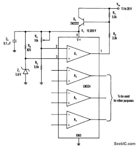
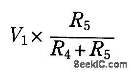
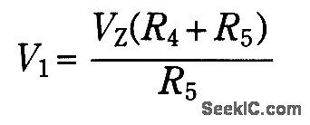


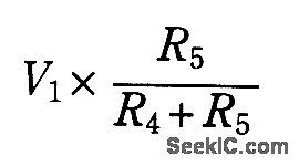
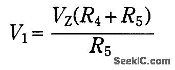

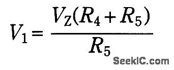
This op amp offers a straightforward method of developing a single-polarity stable voltage source (see the ftgure). Transistor Q1 gets a base drive through resistor R1, and conducts to develop a voltage(V1) across the IC's supply pins. Amp A1, R2, and Q1 form a positive-feedback closed loop, along with R3 and the zener diode. A1, R2, and Q1 also form a negative-feedback closed loop with R4 and R5.The effect of positive feedback is predominant as the noninverting input receives V1while the inverting input receives only: This happens until the zener comes into play. When the voltage at the inverting input exceeds the voltage at the noninverting input, A1's output takes away Q1's base current through R2, which reduces V1.Hence, an equilibrium condition is reached. Now:This circuit can source more than 30 mA.
Reprinted Url Of This Article:
http://www.seekic.com/circuit_diagram/Amplifier_Circuit/OP_AMP_REGULATOR.html
Print this Page | Comments | Reading(3)

Article Categories
power supply circuit
Amplifier Circuit
Basic Circuit
LED and Light Circuit
Sensor Circuit
Signal Processing
Electrical Equipment Circuit
Control Circuit
Remote Control Circuit
A/D-D/A Converter Circuit
Audio Circuit
Measuring and Test Circuit
Communication Circuit
Computer-Related Circuit
555 Circuit
Automotive Circuit
Repairing Circuit
Code: