Amplifier Circuit
Miniature Audio Oscillator
Published:2012/10/18 3:16:00 Author:muriel | Keyword: Miniature , Audio, Oscillator | From:SeekIC

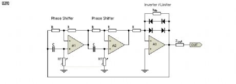
The oscillator circuit (see Figure 1) involves two unity gain phase shift stages, A1 and A2, in tandem and a gain stage, A3, with back to back diodes and resistor network providing non-linear negative feedback. At a particular frequency (determined by RT and CT - the timing components) A1 and A2 provide 90 degrees phase shift each, 180 degrees in total and the circuit begins oscillating, since A3 and its non linear network has more than unity gain for small signals. As the oscillation level increases the diodes conduct and limit the gain of A3 stabilising the output at the desired level, in this case a little over 1V RMS. However, some distortion of the sine wave peaks is caused by the diodes.
Reprinted Url Of This Article:
http://www.seekic.com/circuit_diagram/Amplifier_Circuit/Miniature_Audio_Oscillator.html
Print this Page | Comments | Reading(3)

Article Categories
power supply circuit
Amplifier Circuit
Basic Circuit
LED and Light Circuit
Sensor Circuit
Signal Processing
Electrical Equipment Circuit
Control Circuit
Remote Control Circuit
A/D-D/A Converter Circuit
Audio Circuit
Measuring and Test Circuit
Communication Circuit
Computer-Related Circuit
555 Circuit
Automotive Circuit
Repairing Circuit
Code: