© 2008-2012 SeekIC.com Corp.All Rights Reserved.
Amplifier Circuit
MULTIPLYING_PRECISE_COMMUTATING_AMP
Published:2009/7/9 23:55:00 Author:May | From:SeekIC


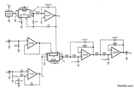
By using a pulse-width-height modulation technique, this circuit implements a 0.015%-accurate multi-plier. The circuit's output equals VXVY/10. An AD581 voltage reference, an AD630 commutating amplifier, and an integrator comprising an AD707 op amp, 2000-pF capacitor, and 150-kΩ resistor first generate a precision triangle wave. For a given state of the AD630's output (+VREF at TP1, for example) the integra-tor ramps until its output reaches -11V. Then, TP) changes state and the integrator begins ramping toward +11V. The triangle wave's period is 4.4RC or 1.32ms, where R and C are the values of the integrator components.
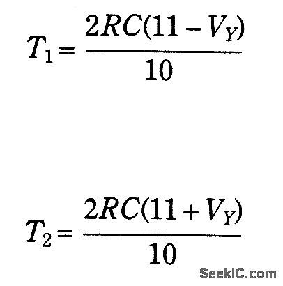
The circuit uses a second AD630, driven by the variable VX to compare the triangle waveform at TP2 to the signal at VY The duty cycle, T1+T2, at the output of this second commutating amplifier is:
During T1, the voltage at TP4 equals -1.1VX. During the remaining period, T2, the pulse height will equal+1.1VX. VOUT is the average, obtained by low-pass filtering, of this T1 and T2 combined waveform and equals:
You can use a higher bandwidth filter and a higher carrier frequency to build a faster multiplier.
Reprinted Url Of This Article:
http://www.seekic.com/circuit_diagram/Amplifier_Circuit/MULTIPLYING_PRECISE_COMMUTATING_AMP.html
Print this Page | Comments | Reading(3)

Article Categories
power supply circuit
Amplifier Circuit
Basic Circuit
LED and Light Circuit
Sensor Circuit
Signal Processing
Electrical Equipment Circuit
Control Circuit
Remote Control Circuit
A/D-D/A Converter Circuit
Audio Circuit
Measuring and Test Circuit
Communication Circuit
Computer-Related Circuit
555 Circuit
Automotive Circuit
Repairing Circuit
New published articles
Response in 12 hours

Code: