Amplifier Circuit
LOW_DRIFT_LOW_NOISE_dc_AMPLIFIER
Published:2009/7/9 21:42:00 Author:May | From:SeekIC

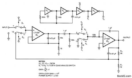
Figure 39-2's circuit combines a low-noise op amp, IC1, with a chopper-based carrier-modulation scheme to achieve a low-noise, low-drift dc amplifier whose performance exceeds any currently available monolithic amplifier. The amplifier's offset is less than 1μV/℃, and its drift is less than 0.05 μV. This circuit has noise within a 10-Hz bandwidth less than 40 nV. The amplifier's bias current, which is set by the bipolar input of IC1, is about 25 nA.
The 74C04 inverters (IC3 to IC6) form a simple 2-phase square-wave clock that runs at about 350 Hz.The complementary oscillator signals (Q1 and Q2) provide drive to S1 and S2,respectively, causing a chopped version of the input to appear at 101's input. IC1 amplifies this ac signal. S3 and S4 synchronously demodulate 101's square-wave output. Because 53 and 54 switch synchronously with S1 and S2, the cir-cuit presents proper amplitude and polarity information to IC2, the dc output amplifier. This output stage integrates the square wave to provide a dc voltage output. R1 and R2 divide the output and feed it back to the input chopper where the divided output serves as a zero signal reference. The ratio of RI and R2 sets the gain, in this case to 1000.
Reprinted Url Of This Article:
http://www.seekic.com/circuit_diagram/Amplifier_Circuit/LOW_DRIFT_LOW_NOISE_dc_AMPLIFIER.html
Print this Page | Comments | Reading(3)

Article Categories
power supply circuit
Amplifier Circuit
Basic Circuit
LED and Light Circuit
Sensor Circuit
Signal Processing
Electrical Equipment Circuit
Control Circuit
Remote Control Circuit
A/D-D/A Converter Circuit
Audio Circuit
Measuring and Test Circuit
Communication Circuit
Computer-Related Circuit
555 Circuit
Automotive Circuit
Repairing Circuit
Code: