Amplifier Circuit
LINEAR_OUTPUT_RAMP
Published:2009/7/14 20:42:00 Author:May | From:SeekIC

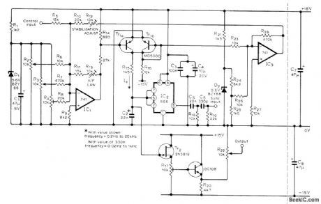
Provides high frequency stability as required for use in sound synthesizers. Can be synchronized to another oscillator. Uses 555 timer in astable mode, with Tr1a supplying constant current to C2. R12 and R13 should be multiturn pots. Synchronizing square-wave signal having 5-10 V peak can be fed in at R19 for differentiation, and resulting spikes used to control threshold voltage of 555. R4 sets minimum frequency. R22 sets average Output level to 0 V R2 and R3 serve as coarse and fine frequency controls Tr1 can also be BFX11 or BFX36. –T. W. Stride, Voltage Controlled Oscillator Wireless World, Oct . 1977, p 66.
Reprinted Url Of This Article:
http://www.seekic.com/circuit_diagram/Amplifier_Circuit/LINEAR_OUTPUT_RAMP.html
Print this Page | Comments | Reading(3)

Article Categories
power supply circuit
Amplifier Circuit
Basic Circuit
LED and Light Circuit
Sensor Circuit
Signal Processing
Electrical Equipment Circuit
Control Circuit
Remote Control Circuit
A/D-D/A Converter Circuit
Audio Circuit
Measuring and Test Circuit
Communication Circuit
Computer-Related Circuit
555 Circuit
Automotive Circuit
Repairing Circuit
Code: