Amplifier Circuit
How to Move a Trip Point of Op-Amp Comparator Circuits
Published:2013/11/12 20:02:00 Author:lynne | Keyword: Op-Amp Comparator | From:SeekIC

You all will befamiliar of basic comparator using a Op-Amp circuit. So today we will show you how to move a trip point of a Op-Amp comparator circuit. Maybe many of people already know this, but still this is the post forbeginners. So if you already know quit reading now only.
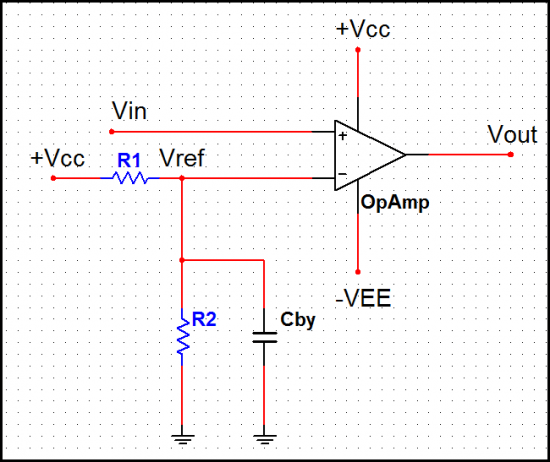
As shown in the above circuit, by application of a reference voltage to the inverting input rather than grounding it the trip can be moved. The reference voltage is given to the inverting input of a basic comparator using a potential divider consisting of resistors R1 and R2. The reference voltage Vref is derived using +Vcc and potential divider R1 and R2. Mathematically Vref is expressed as,
Vref = [+Vcc/(R1+R2)] R2
Now as long as the input voltage is less than Vref, the output is low i.e. -Vsat. When Vin becomes slightly greater than Vref, the Op-Amp output becomes high i.e. +Vsat. Thus the trip point is moved from Vin = 0 to Vin = Vref due to reference voltage applied to the inverting input terminal.
A bypass capacitor is used on the inverting input to reduce the amount of power supply ripple and noise appearing at the inverting input of Op-Amp. For effective bypassing of ripple and noise, the critical frequency of bypass circuit must be much lower than the ripple frequency of power supply.
The transfer characteristics of such a comparator is shown in above diagram which indicates positive trip point. Such a comparator is also called a limit detector as it detects the particular positive level of the input beyond which input goes high. The resistance R1 and R2 can be used to set the trip point anywhere between 0 and +Vcc.
The cut-off frequency of bypass circuit is,
fc = 1/[ 2π(R1||R2) Cby.
This must be much lower than the ripple frequency of the supply.
Reprinted Url Of This Article:
http://www.seekic.com/circuit_diagram/Amplifier_Circuit/How_to_Move_a_Trip_Point_of_Op_Amp_Comparator_Circuits.html
Print this Page | Comments | Reading(3)

Article Categories
power supply circuit
Amplifier Circuit
Basic Circuit
LED and Light Circuit
Sensor Circuit
Signal Processing
Electrical Equipment Circuit
Control Circuit
Remote Control Circuit
A/D-D/A Converter Circuit
Audio Circuit
Measuring and Test Circuit
Communication Circuit
Computer-Related Circuit
555 Circuit
Automotive Circuit
Repairing Circuit
Code: