Amplifier Circuit
Floating_voltage_controlled_resistor
Published:2009/7/17 3:08:00 Author:Jessie | From:SeekIC
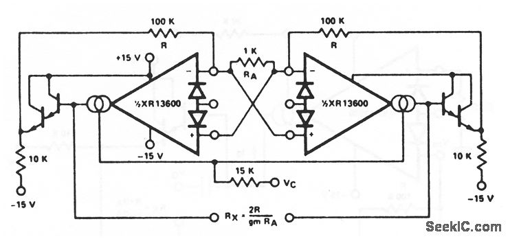
This circuit is similar to that of Fig. 11-6, except that both sections of the XR-13600 (Fig. 11-1B) are used. Each end of the resistor can be at any voltage within the output range of the XR- 13600. EXAR Corporation Databook 1990 p 5-254
Reprinted Url Of This Article:
http://www.seekic.com/circuit_diagram/Amplifier_Circuit/Floating_voltage_controlled_resistor.html
Print this Page | Comments | Reading(3)

Article Categories
power supply circuit
Amplifier Circuit
Basic Circuit
LED and Light Circuit
Sensor Circuit
Signal Processing
Electrical Equipment Circuit
Control Circuit
Remote Control Circuit
A/D-D/A Converter Circuit
Audio Circuit
Measuring and Test Circuit
Communication Circuit
Computer-Related Circuit
555 Circuit
Automotive Circuit
Repairing Circuit
Code: