Amplifier Circuit
Digitally_controlled_variable_gain_amplifier
Published:2009/7/24 23:21:00 Author:Jessie | From:SeekIC

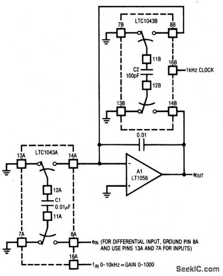
This circuit provides a continuously-variable gain from 0 to 1000, with a stability of 20 ppm/℃. Either a single-ended or differential input can be selected.A host processor selects the desired gain by applying the corresponding frequency at pin 16A of the LTC1043A. The LTC1043B is continuously clocked by a 1-kHz source (which can also be supplied by the host processor). For the values given, gain is: (fIN×10) × (0.01 μF/100 pF). Gain stability depends on the ratiometric stability between the 1-kHz clock and the variable clock (pin 16A). For this reason, both the fixed and variable clocks should be supplied by the same source (probably a processor).
Reprinted Url Of This Article:
http://www.seekic.com/circuit_diagram/Amplifier_Circuit/Digitally_controlled_variable_gain_amplifier.html
Print this Page | Comments | Reading(3)

Article Categories
power supply circuit
Amplifier Circuit
Basic Circuit
LED and Light Circuit
Sensor Circuit
Signal Processing
Electrical Equipment Circuit
Control Circuit
Remote Control Circuit
A/D-D/A Converter Circuit
Audio Circuit
Measuring and Test Circuit
Communication Circuit
Computer-Related Circuit
555 Circuit
Automotive Circuit
Repairing Circuit
Code: