Amplifier Circuit
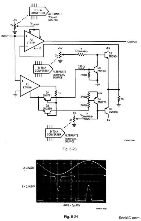
Differential_comparator_amplifier_with_adjustable_limiting_and_offset
Published:2009/7/24 20:59:00 Author:Jessie | From:SeekIC

Figure 5-23 is similar to Fig. 5-21, except that the dual channels permit observations of information between two adjustable amplitude-defined points. The set points are adjustable in both magnitude and sign. In the circuit of Fig. 5-23, the polarity of the offset applied to the A2 inverting input is determined by the comparator A1 output state. Figure 5-24 shows the circuit output for a sine input (trace A). The +VCOMPARE and -VCOMPARE voltages are set just below the sine-wave peaks, with VCLAMP set to restrict amplification to the peak excursion. The circuit output (trace B) simultaneously shows the amplitude detail of both sine peaks. LINEAR TECHNOLOGY, APPLICATION NOTE 47, P. 40, 41.
Reprinted Url Of This Article:
http://www.seekic.com/circuit_diagram/Amplifier_Circuit/Differential_comparator_amplifier_with_adjustable_limiting_and_offset.html
Print this Page | Comments | Reading(3)

Article Categories
power supply circuit
Amplifier Circuit
Basic Circuit
LED and Light Circuit
Sensor Circuit
Signal Processing
Electrical Equipment Circuit
Control Circuit
Remote Control Circuit
A/D-D/A Converter Circuit
Audio Circuit
Measuring and Test Circuit
Communication Circuit
Computer-Related Circuit
555 Circuit
Automotive Circuit
Repairing Circuit
Code: