Amplifier Circuit
CURRENT_PROBE_AMPLIFIER
Published:2009/6/24 3:02:00 Author:May | From:SeekIC

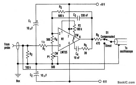
A clamp-on current probe, such as the Tektronix P6021, is a useful means of displaying current waveforms on an oscilloscope. A less-expensive and simple alternative is shown in the figure.The more sensitive range on the P6021 is 2 mA/mV, but it has a roll-off of 6-dB per octave below 450 Hz. The purpose of the compensator is to counteract the low-frequency attenuation, which is achieved by means of C3 and R4 + P1 in the feedback around op amp N1. It's important that the latter is a low-noise type, such as the LM725 shown in the figure. On top of that, it's necessary at some point to limit the increasing gain with decreasing frequency; otherwise, amplifier noise and drive will overcome the signal. The values shown for C3 and R3 give a lower limit of less than 1 Hz.A test square wave of ±1 mA is fed to the current probe so that P1 can be adjusted for minimum droop or overshoot in the output waveform. It's vital that the sliding core on the probe is fully closed. At high frequencies, the response begins to fall off at 100 kHz. Therefore, for most waveforms, switch S1 is moved to direct, above a fundamental frequency of, for example, 10 kHz.This circuit's current consumption is quite low, and it can be battery powered. If a mains power supply is built-in, it must be well screened to prevent hum problems.
Reprinted Url Of This Article:
http://www.seekic.com/circuit_diagram/Amplifier_Circuit/CURRENT_PROBE_AMPLIFIER.html
Print this Page | Comments | Reading(3)

Article Categories
power supply circuit
Amplifier Circuit
Basic Circuit
LED and Light Circuit
Sensor Circuit
Signal Processing
Electrical Equipment Circuit
Control Circuit
Remote Control Circuit
A/D-D/A Converter Circuit
Audio Circuit
Measuring and Test Circuit
Communication Circuit
Computer-Related Circuit
555 Circuit
Automotive Circuit
Repairing Circuit
Code: