Amplifier Circuit
Basic inverting amplifier circuit composed of the μA709
Published:2011/8/22 22:10:00 Author:Rebekka | Keyword: Basic inverting amplifier | From:SeekIC


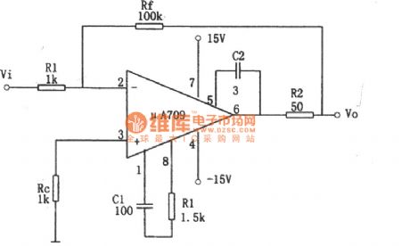
The figure of the basic inverting amplifier circuit composed of the μA709 is shown as above.
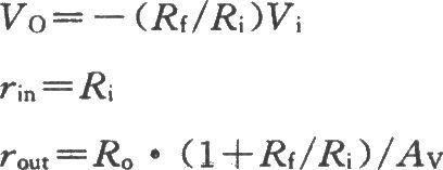
The main performance of the U A709 :
According to the figure, the feedback resistor Rf will connect the output and input ends. Since the circuit output, input voltage are inverting, the Rf leads the voltage parallel negative feedback. Thereby the amplifier works in linear region with the op-amp transmission characteristics, that is, the output voltage is proportional to the input voltage. In addition, the inverting input end is connected to the resistor Ri in series, and it is the operational amplifier's input resistor. The increasing of Ri can reduce the source of the load.
Reprinted Url Of This Article:
http://www.seekic.com/circuit_diagram/Amplifier_Circuit/Basic_inverting_amplifier_circuit_composed_of_the_μA709.html
Print this Page | Comments | Reading(3)

Article Categories
power supply circuit
Amplifier Circuit
Basic Circuit
LED and Light Circuit
Sensor Circuit
Signal Processing
Electrical Equipment Circuit
Control Circuit
Remote Control Circuit
A/D-D/A Converter Circuit
Audio Circuit
Measuring and Test Circuit
Communication Circuit
Computer-Related Circuit
555 Circuit
Automotive Circuit
Repairing Circuit
Code: