Amplifier Circuit
Amplifier_with_10_dB_gain_over_nine_octaves
Published:2009/7/23 23:16:00 Author:Jessie | From:SeekIC


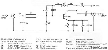
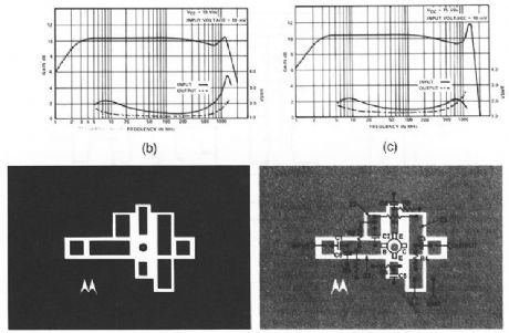
This circuit has a gain of about 10 dB from 3 MHz to over 1GHz (Fig.2-59B). The gain/VSWR versus frequency, PC-board photomaster, and parts layout are shown in Figs. 2-59C, 2-59D, and 2-59E, respectively. The actual layout dimensions are: 1.8 x 1.2 . Two type OSM215 50-Ω input and output connectors can be mounted opposite to the component side of the board, if required.
Reprinted Url Of This Article:
http://www.seekic.com/circuit_diagram/Amplifier_Circuit/Amplifier_with_10_dB_gain_over_nine_octaves.html
Print this Page | Comments | Reading(3)

Article Categories
power supply circuit
Amplifier Circuit
Basic Circuit
LED and Light Circuit
Sensor Circuit
Signal Processing
Electrical Equipment Circuit
Control Circuit
Remote Control Circuit
A/D-D/A Converter Circuit
Audio Circuit
Measuring and Test Circuit
Communication Circuit
Computer-Related Circuit
555 Circuit
Automotive Circuit
Repairing Circuit
Code: