Amplifier Circuit
AM_MODULATOR_LIMITING_AMPLIFIER
Published:2009/7/17 3:50:00 Author:Jessie | From:SeekIC

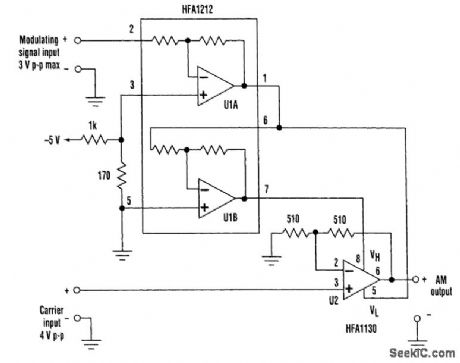
Limiting amplifiers also can be put to work in AM modulators. The fast overdrive recovery time and wide bandwidth of the clamp inputs allows these inputs to be driven by high-frequency ac, can as well as dc signals. When driven at the appropriate levels, the clamp inputs can be used to form an amplitude modulator. The HFA1130 limiting amplifier is driven by a 4-V p-p carrier signal. The gain of 2 through the HFA1130 ensures that the carrier amplitude is sufficient to drive the output over its±3.3-V range. The HFA1212 performs the necessary level shifting and inversion to convert the modulating signal input into a pair of antiphase signals that control the high and low clamp inputs. U1A inverts the signal and level-shifts to -1.5 V. U1B inverts that signal, forming a complementary signal centered at + 1.5 V. With a signal input of 0 V, U2 produces a 3-V p-p output at the carrier frequency. As the signal input varies, U2 produces a symmetrically modulated carrier with a maximum ampli-tude of6 V p-p. The 2300-V/μs slew rate of the HFA1130 limits 6-V p-p amplitude carrier signals to a frequency of 61 MHz. If adjusted for lower output-signal levels, the carrier and modulating frequencies can be increased to well above 100 MHz.
Reprinted Url Of This Article:
http://www.seekic.com/circuit_diagram/Amplifier_Circuit/AM_MODULATOR_LIMITING_AMPLIFIER.html
Print this Page | Comments | Reading(3)

Article Categories
power supply circuit
Amplifier Circuit
Basic Circuit
LED and Light Circuit
Sensor Circuit
Signal Processing
Electrical Equipment Circuit
Control Circuit
Remote Control Circuit
A/D-D/A Converter Circuit
Audio Circuit
Measuring and Test Circuit
Communication Circuit
Computer-Related Circuit
555 Circuit
Automotive Circuit
Repairing Circuit
Code: