Amplifier Circuit
5 Watts FM RF Amplifier
Published:2012/11/13 21:53:00 Author:muriel | Keyword: 5 Watts , FM, RF Amplifier | From:SeekIC

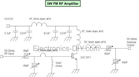
This fm rf amplifier uses 2SC1971 transistor to provide 5 watts of output. Output matching is adjusted via the two 40pF trimmer capacitors likewise also to the input. Note that the emitter of this transistor is directly grounded on the heat sink and should have a good thermal transfer. Driving power of 100 to 200mW can be applied in order to provide 5watts of output. Use a dummy load to tune this amplifier and remember that the transistor is biased in Class C, sufficient filtering should be followed after the output to minimize all the harmonics. Use ground plane construction technique in the PCB lay-out for best result, the more the grounding the better. If you have hard time finding the 10uH rf choke, try to wind 1/2 meter of 0.2mm enamel wire over a 33K 1/2 watt resistor and solder the coil ends to the legs of the resistor.
Reprinted Url Of This Article:
http://www.seekic.com/circuit_diagram/Amplifier_Circuit/5_Watts_FM_RF_Amplifier.html
Print this Page | Comments | Reading(3)

Article Categories
power supply circuit
Amplifier Circuit
Basic Circuit
LED and Light Circuit
Sensor Circuit
Signal Processing
Electrical Equipment Circuit
Control Circuit
Remote Control Circuit
A/D-D/A Converter Circuit
Audio Circuit
Measuring and Test Circuit
Communication Circuit
Computer-Related Circuit
555 Circuit
Automotive Circuit
Repairing Circuit
Code: