Amplifier Circuit
400_Hz_SERVO_AMPLIFIER
Published:2009/7/5 21:47:00 Author:May | From:SeekIC

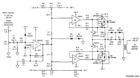
The signal from a synchro receiver or a variable resistive cam follower (potentiometer) is boosted by operational amplifier U1, whose output swing is limited by back-to-back zeners D3 and D4. The signal is then applied to operational amplifiers U2 and U3, which drive the gates of Q1 and Q2 respectively. The npn transistor (Q3) is a fast current limiter for the n-channel MTM8N10; a pnp transistor (Q4) performs the same function for the p-channel MTM8P10. Capacitors C3 and C4 eliminate the need for accurate dc offset zeroing. T1 steps up the output voltage to 120 V for the 400 Hz servo motor.
Reprinted Url Of This Article:
http://www.seekic.com/circuit_diagram/Amplifier_Circuit/400_Hz_SERVO_AMPLIFIER.html
Print this Page | Comments | Reading(3)

Article Categories
power supply circuit
Amplifier Circuit
Basic Circuit
LED and Light Circuit
Sensor Circuit
Signal Processing
Electrical Equipment Circuit
Control Circuit
Remote Control Circuit
A/D-D/A Converter Circuit
Audio Circuit
Measuring and Test Circuit
Communication Circuit
Computer-Related Circuit
555 Circuit
Automotive Circuit
Repairing Circuit
Code: