Amplifier Circuit
30_W_150__to_175_MHz_amplifier
Published:2009/7/23 23:08:00 Author:Jessie | From:SeekIC


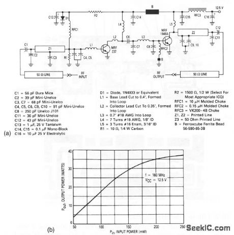
This circuit produces an overall gain in excess of20 dB (Fig. 2-56B).Figure 2-56C shows typical parts placement, and Fig. 2-56D shows the PC-board photomaster (actual dimensions: 5 x 2 ). The amplifier is constructed on 1/16 , double-sided G-10 board with 2-ounce copper cladding. The top and bottom ground planes of the board are connected by wrapping the board edges with thin copper foil (0.002 ) and then soldering the foil in place. The MRF237 is inserted into a hole in the board and soldered to the ground plane for heatsinking. The MRF1946A is mounted on a conventional heatsink (an 8-32 stud inserted into an appropriately prepared heatsink). Refer to Motorola AN778 and AN790 for mounting and thermal ratings of power transistors.
Reprinted Url Of This Article:
http://www.seekic.com/circuit_diagram/Amplifier_Circuit/30_W_150__to_175_MHz_amplifier.html
Print this Page | Comments | Reading(3)

Article Categories
power supply circuit
Amplifier Circuit
Basic Circuit
LED and Light Circuit
Sensor Circuit
Signal Processing
Electrical Equipment Circuit
Control Circuit
Remote Control Circuit
A/D-D/A Converter Circuit
Audio Circuit
Measuring and Test Circuit
Communication Circuit
Computer-Related Circuit
555 Circuit
Automotive Circuit
Repairing Circuit
Code: