Amplifier Circuit
1.8_to_72_MHz_POWER_AMPLIFIER
Published:2009/7/13 2:38:00 Author:May | From:SeekIC


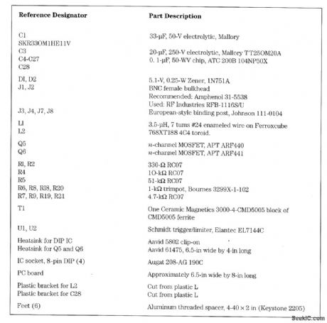
A novel approach to a 250-W power amplifier (PA) is shown. The driver uses a pair of low-cost ICs, rather than the conventional RF transformer to provide out-of-phase driving signals for the two final MOSFETs. It also provides hard limiting (sine -wave-to-square -wave conversion) of the input signal. The Elantec EL7144C is intended for use as a gate driver. The internal Schmidt trigger allows it to serve as a hard limiter, and the presence of both inverting and noninverting inputs allows a pair to serve as a phase splitter. The RF input is ac-coupled to the noninverting input of U1 and the inverting input of U2. Adjustment of the biases via R6 and R8 allows the transition points to be selected to produce the desired duty ratio (50:50). The phase error between the two EL7144s is about 0.5 ns. (If an oscilloscope is not available, use a voltmeter with a 1-kΩ series resistor and setthe average output voltage to 6 V.) The EL7144s have high input impedances, so R5 provides a 50-V input impedance for the signal source. Input signals in the range of 10 to 100 mW are satisfactory, allowing this PA to be driven directly from a laboratory signal generator or oscillator with buffer.The best switching speed is obtained with VDD1=12 V. Output transistors are ARF440 and ARF441.See parts list.
Reprinted Url Of This Article:
http://www.seekic.com/circuit_diagram/Amplifier_Circuit/1.8_to_72_MHz_POWER_AMPLIFIER.html
Print this Page | Comments | Reading(3)

Article Categories
power supply circuit
Amplifier Circuit
Basic Circuit
LED and Light Circuit
Sensor Circuit
Signal Processing
Electrical Equipment Circuit
Control Circuit
Remote Control Circuit
A/D-D/A Converter Circuit
Audio Circuit
Measuring and Test Circuit
Communication Circuit
Computer-Related Circuit
555 Circuit
Automotive Circuit
Repairing Circuit
Code: