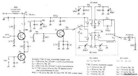
Amplifier Circuit
1_W_EXCITER_FOR_7_AND_14_MHz
Published:2009/7/8 4:25:00 Author:May | From:SeekIC

Developedfor use in simple solid-state VFO transmittercovering 40 and 20 meters for low-power operation Adequate drive can be provided by any 7-MHz VFO that develops 0.45 VRMS across 1000-ohm load. Circuit consists of olass A bufferl amplifier Q1 and keying switch Q2. Q3 is class C amplifier on 7 MHz (40m) and frequency doubler on 14 MHz (20m). Q1 is MPS6514. Q2 is 2N3906 or equivalent, Q3 is MPS-U31. All trans-former cores are Amidon T-50-2.—A. Weiss, QRP, CQ Nov. 1971, p 54-58 and 88.
Reprinted Url Of This Article:
http://www.seekic.com/circuit_diagram/Amplifier_Circuit/1_W_EXCITER_FOR_7_AND_14_MHz.html
Print this Page | Comments | Reading(3)

Article Categories
power supply circuit
Amplifier Circuit
Basic Circuit
LED and Light Circuit
Sensor Circuit
Signal Processing
Electrical Equipment Circuit
Control Circuit
Remote Control Circuit
A/D-D/A Converter Circuit
Audio Circuit
Measuring and Test Circuit
Communication Circuit
Computer-Related Circuit
555 Circuit
Automotive Circuit
Repairing Circuit
Code: