Amplifier Circuit
1_Hz_TIMEBASE_FOR_READOUT_AND_COUNTER_APPLICATIONS
Published:2009/7/9 4:08:00 Author:May | From:SeekIC

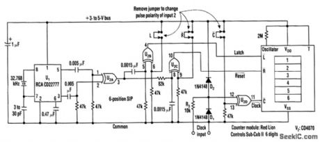
This counter makes direct readout of frequency-generating equipment very easy when a 1-Hz time-base is added to latch, reset, and the count signal is conditioned. This design has the flexibility to select either polarity.
By differentiating, inverting, and ORing the clock pulses in XOR gate U2A, a stream of 1-Hz, positive, 200-μs pulses is generated. For latching, the 1-Hz stream is again differentiated in U2B, input 1 to supply a 50-μs pulse. Though U2B's output goes from high to low, it can be reversed, by making input 2 low.
Because the reset pulse must occur after the latch signal, the 1-Hz stream from U2A is delayed 100 μs at U2C input 1. The output-pulse polarity is determined by making U2C's input 2 either high or low.
Reprinted Url Of This Article:
http://www.seekic.com/circuit_diagram/Amplifier_Circuit/1_Hz_TIMEBASE_FOR_READOUT_AND_COUNTER_APPLICATIONS.html
Print this Page | Comments | Reading(3)

Article Categories
power supply circuit
Amplifier Circuit
Basic Circuit
LED and Light Circuit
Sensor Circuit
Signal Processing
Electrical Equipment Circuit
Control Circuit
Remote Control Circuit
A/D-D/A Converter Circuit
Audio Circuit
Measuring and Test Circuit
Communication Circuit
Computer-Related Circuit
555 Circuit
Automotive Circuit
Repairing Circuit
Code: