Amplifier Circuit
1296_MHz_SOLID_STATE_POWER_AMPLIFIER
Published:2009/7/9 22:48:00 Author:May | From:SeekIC

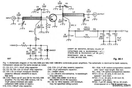
The design incorporates 30-Ω,1/4λmicrostrip lines on the input and output.C3,C4,C7,and C8,along with L1, from a pi network that matches the low-input impedance ofthe device to 50 Ω.C5,C6,C9,C10,and 30-Ω transmission line L2 form an outputpl network that maxlmlzes power transfer to 50 Ω.C10 is not always necessary, depending on variations among devices and circuitboard material.Bias is provided by R1,R2,and D1.R1 can be optimized, if desired,to adjust the collector idling current.
Reprinted Url Of This Article:
http://www.seekic.com/circuit_diagram/Amplifier_Circuit/1296_MHz_SOLID_STATE_POWER_AMPLIFIER.html
Print this Page | Comments | Reading(3)

Article Categories
power supply circuit
Amplifier Circuit
Basic Circuit
LED and Light Circuit
Sensor Circuit
Signal Processing
Electrical Equipment Circuit
Control Circuit
Remote Control Circuit
A/D-D/A Converter Circuit
Audio Circuit
Measuring and Test Circuit
Communication Circuit
Computer-Related Circuit
555 Circuit
Automotive Circuit
Repairing Circuit
Code: