Amplifier Circuit
10_dB_GAIN_AMPLIFIER
Published:2009/7/9 22:50:00 Author:May | From:SeekIC

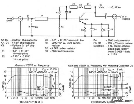
This circuit design is a class A amplifier employing both ac and dc feedback. Bias is stabilized at 15 mA of the collector current using dc feedback from the collector. The ac feedback, from collector to base, and in each of the partially bypassed emitter circuits, compensates for the increase in device gain with decreasing frequency, yielding a flat response over a maximum bandwidth. The amplifter shows a nominal 10-dB power gain from 3 MHz to 1.4 GHz. With only a minimum matching network used at the amplifier input, the input VSWR remains less than 2.5:1 to approximately 1 GHz, while the output VSWR stays under 2:1. Note that a slight degradation in gain flatness and output VSWR occurs with the addition of C6. A more elaborate network design would probably optimize impedance matching, while maintaining gain flatness.
Reprinted Url Of This Article:
http://www.seekic.com/circuit_diagram/Amplifier_Circuit/10_dB_GAIN_AMPLIFIER.html
Print this Page | Comments | Reading(3)

Article Categories
power supply circuit
Amplifier Circuit
Basic Circuit
LED and Light Circuit
Sensor Circuit
Signal Processing
Electrical Equipment Circuit
Control Circuit
Remote Control Circuit
A/D-D/A Converter Circuit
Audio Circuit
Measuring and Test Circuit
Communication Circuit
Computer-Related Circuit
555 Circuit
Automotive Circuit
Repairing Circuit
Code: