A/D-D/A Converter Circuit
WIDE_BANDWIDTH_VOLTAGE_TO_FREQUENCY_CONVERTER
Published:2009/7/14 22:47:00 Author:Jessie | From:SeekIC
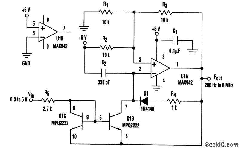
Shown is the design for a low-cost, wide-bandwidth voltage-to-frequency converter (VFC). The core element of the prototype VFC is a Maxim MAX942 high-speed comparator. When operating, R1, R2, and R3 provide hysteresis with trip points from one-third to two-thirds of the supply voltage.This permits wide adjustability in the width of the output pulse. Q1C and Q1B form a current mirror that linearizes the charge potential across C2. As the voltage at pin 2 of U1 crosses the lower trip point, the comparator output turns on. The current mirror sink node is raised above the program voltage, which turns it off. D1 turns on, removing the charge on C2 through R4. When the voltage at U1 pin 2 crosses the upper trip point, the circuit resets. Upon observation, the prototype circuit linearity was approximately 2 percent over the tested range. Also, up to 6-MHz operation was possible using the MAX942 by carefully selecting C2 and the hysteresis resistors. Discrete transistors can be used instead of the Motorola MPQ2N2222 monolithic quad package. This can cause some instability at low frequencies. The transistors should be located in close thermal proximity. On the high side, a good, matched transistor pair can be used. Analog Devices' MAT-01 is a good choice.
Reprinted Url Of This Article:
http://www.seekic.com/circuit_diagram/A-D_D-A_Converter_Circuit/WIDE_BANDWIDTH_VOLTAGE_TO_FREQUENCY_CONVERTER.html
Print this Page | Comments | Reading(3)

Article Categories
power supply circuit
Amplifier Circuit
Basic Circuit
LED and Light Circuit
Sensor Circuit
Signal Processing
Electrical Equipment Circuit
Control Circuit
Remote Control Circuit
A/D-D/A Converter Circuit
Audio Circuit
Measuring and Test Circuit
Communication Circuit
Computer-Related Circuit
555 Circuit
Automotive Circuit
Repairing Circuit
Code: