A/D-D/A Converter Circuit
VLF_CONVERTER
Published:2009/7/10 0:45:00 Author:May | From:SeekIC

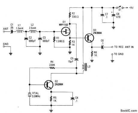
The VLF Converter can be used to pick up signals for the general coverage of shortwave receivers. A number of unusual signals can be heard on frequencies below 15 kHz.This converter wiil convert frequencies from 0 to 250 kHz to 3500 to 3750 kHz so that the LF- and VLF-band segments can be received on an amateur or shortwave receiver that covers 3 500 to 4000 kHz.Signals from a short whip antenna (8 to 10 feet) are coupled through low-pass filter L1/L2/C2/C3 to RF amp Q1. Q3 mixes these signals with a 3.5-MHz signal from Q2 and associated components C4, R5, R4, and 3.5-MHz XTAL. L3 is an RF choke that presents an inductive load to Q3. It should be resonant some-what above 3.5 MHz when placed in the circuit. An adjustable coil of about 30 to 100 μH should be suffi-cient. The converter output is taken from the emitter of Q3 through C6.
Reprinted Url Of This Article:
http://www.seekic.com/circuit_diagram/A-D_D-A_Converter_Circuit/VLF_CONVERTER.html
Print this Page | Comments | Reading(3)

Article Categories
power supply circuit
Amplifier Circuit
Basic Circuit
LED and Light Circuit
Sensor Circuit
Signal Processing
Electrical Equipment Circuit
Control Circuit
Remote Control Circuit
A/D-D/A Converter Circuit
Audio Circuit
Measuring and Test Circuit
Communication Circuit
Computer-Related Circuit
555 Circuit
Automotive Circuit
Repairing Circuit
Code: