D/A Converter
ISOLATED_3_V_TO_5_V_DAC
Published:2009/7/12 22:50:00 Author:May | From:SeekIC
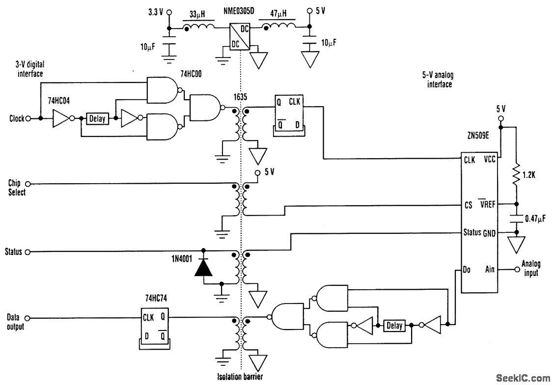


The circuit uses a low-power (1 W) dc-to-dc converter for the power isolation and a transformer isolator/translator for the data interface. The transformer isolator not only provides the galvanic iso-lation required, but also converts the data signals between 3-V and 5-V levels. As a result, no additional level conversion is required. The ADC can run at 1-MHz clock rates. To allow the 50 percent duty cycles (clock and data signals) to pass through a transformer isolator requires an edge-detection and conversion technique. The edge detector is built from simple logic gates (two inverters and three NAND gates) and a short delay (either a delay line or a passive RC circuit can be used). The signal is rebuilt with a D-type flip-flop. Using a four-channel isolator allows full control over the ADC to be exercised. Conversion is requested by pulling the Chip Select pin low, and a Status high for one clock cycle is reported back to acknowledge conversion start. The first data bit (MSB) then is presented onto the data line, and all eight bits are transferred with a further Status signal at the end of conversion. Conversion can be requested asynchronously with the system clock, if necessary, and the Status flag can be used to poll the controlling logic circuitry. Filtering is placed on either side of the dc-to-dc converter to reduce power-supply ripple and prevent noise on the logic power supply from affecting the analog system. Although not shown, all ICs have 0.22-μF decoupling capacitors.
Reprinted Url Of This Article:
http://www.seekic.com/circuit_diagram/A-D_D-A_Converter_Circuit/D-A_Converter/ISOLATED_3_V_TO_5_V_DAC.html
Print this Page | Comments | Reading(3)

Article Categories
power supply circuit
Amplifier Circuit
Basic Circuit
LED and Light Circuit
Sensor Circuit
Signal Processing
Electrical Equipment Circuit
Control Circuit
Remote Control Circuit
A/D-D/A Converter Circuit
Audio Circuit
Measuring and Test Circuit
Communication Circuit
Computer-Related Circuit
555 Circuit
Automotive Circuit
Repairing Circuit
Code: